Amplifier and Wiring Installation Details
All of my photos during the initial installation were lost due to a hard drive crash. I took some new ones, for what it's worth, but all my views of the disassembly of the sill panel, under the dash, and inside the doors are gone. Some images are linked to others that show more detail.
Here were my initial specification requirements:
1. The system must always be powered, i.e., do NOT use the "ignition"
terminal. It must work when the car is off (I will turn the system off manually).
2. Receiver is to be mounted in lower hole in dash, EQ in upper hole - this
avoids problems loading discs when cup holder is out.
3. All line level EQ outputs must be brought to the trunk, including those that
are not currently used. This includes the six line outputs (LF/LR/Lsub, RF/RR/RSub)
from the EQ. The unused outputs can just be capped off in the trunk so they
don't short out anything.
4. Hook up the equalizer's inputs to the CD player's front outputs. No RCA cable
will be needed because the correct plugs are part of the equalizer and can be
plugged directly into the CD player's output jacks.
5. The head unit rear channel speaker outputs will be connected to the existing
speakers in the rear doors. I will not currently be using an amp on the rear
channels. However, see note 6.
6. The head unit rear channel speaker outputs should be labelled on the wires
behind it. In the event that I add a rear channel amplifier, I want to be able
to easily find the wires and disconnect them without tracing them.
7. Run a set of wires for the rear door speakers to the trunk area, even though
no amp is currently being used. If I choose to add a rear channel amp, the only
modifications should be behind the receiver (disconnecting its labelled rear
speaker outputs from the rear speakers) - I should not have to run any wiring
(speaker or line) through the car. You may run them back from where they are
connected in the dash (behind/to) the cd player's speaker outputs). Note: due
to difficulty getting wires under the sill trim, I did not meet this requirement.
8. Use 4-gauge amplifier power wiring to support existing equipment. The speaker
wiring must be sufficiently large to carry the full RMS signal level (2x185W
+ 100W).
9. The large inline fuse at the battery terminal (for the power wiring) must
be replaceable with reasonable effort (i.e., no soldering).
10. Leave enough extra wire length in the trunk so I can fold the rear seat
(on which the amps are mounted) forward.
In summary:
3 stereo RCA line outs (front, rear, sub) from EQ outputs to the electronics
panel.
6 pairs speaker wiring (+ and - for three speakers on each side).
1 remote wire from the EQ.
Connect the CD player rear speaker outputs to the rear speakers (using the factory
harness).
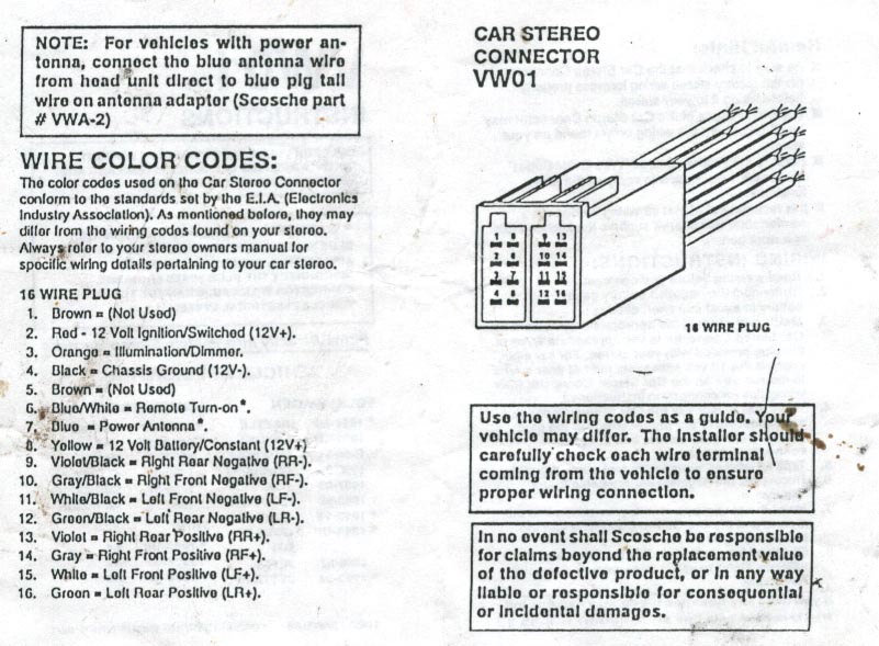
I checked the wiring diagram I received with my Scosche "VW01" car stereo connector and found it to be correct:
This connector mates to the connector that attached the car wiring to the factory stereo. I didn't use all of the connections on it and cut off the tinned ends of the unused ones and carefully taped them off. I connected the rear speaker outputs from the JVC CD player directly to the terminals for the right rear speakers which are mounted in the doors.
The Impulse Audio RCA cables have an orientation. Read the instructions and follow the recommendation, "Connect right angle plugs to radio and straight plugs to amplifier."
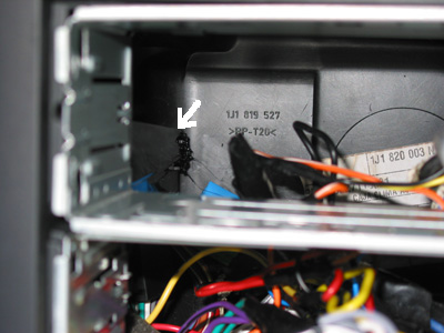
View of the dash with the head units partially removed:
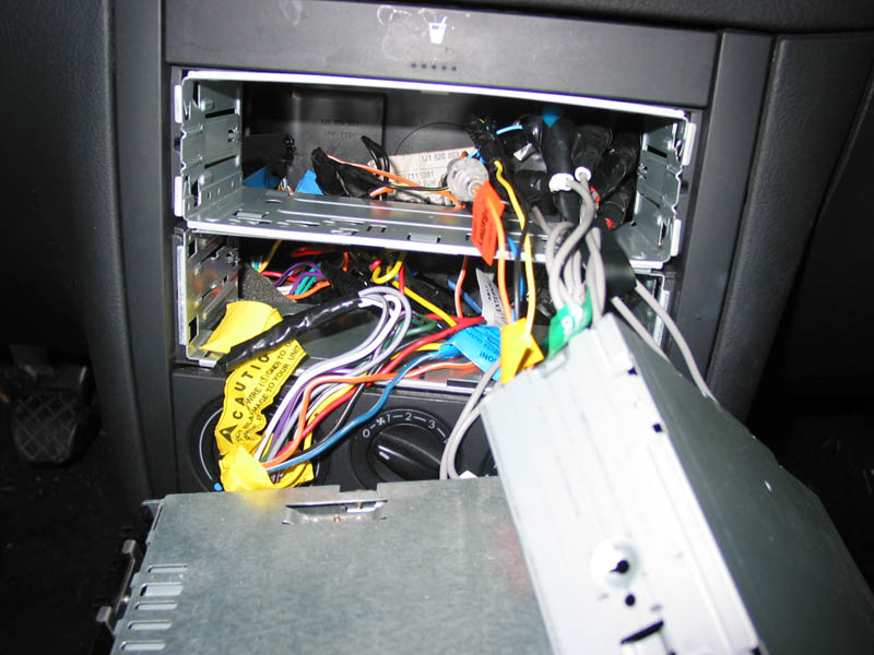
Here is a closer view through the upper hole where you can see where the plastic rib used to be (white arrow). The rib was black plastic and ran behind the factory radio. There wasn't enough room in there to fit in all the wiring, so I removed it by carefully cutting it with the tip of a soldering pencil. The heat cut the plastic quite easily (and besides, there really was no way to get any cutting tools back in there). After about one day, the smell of smoke went away, so don't worry about the car smelling like burning plastic. A fan can be used to suck the smoke out while you are cutting (it does smoke quite a bit). Be careful not to touch the hot tip to the dashboard, heater box, etc. because it will instantly damage the plastic. After this modification, the rear clearance behind the head units extends all the way back to the heater box. I can't remember if there was a plastic rib behind both holes, but I do recall making several short cuts and removing the plastic rib in pieces. It's then possible to fit the wiring in behind the units, although you still have to fool around under the dash to even them out so they units snap into place without forcing.
The cup holder is easily removed by folding up the trim panel and pressing in the two retaining clips at the left and right edges of the cup holder. This releases it and you can pull out the cup holder assembly.
Then in the back of the car...
This is view of the electronics panel before I cleaned up the wiring mess (right rear seat folded forward):
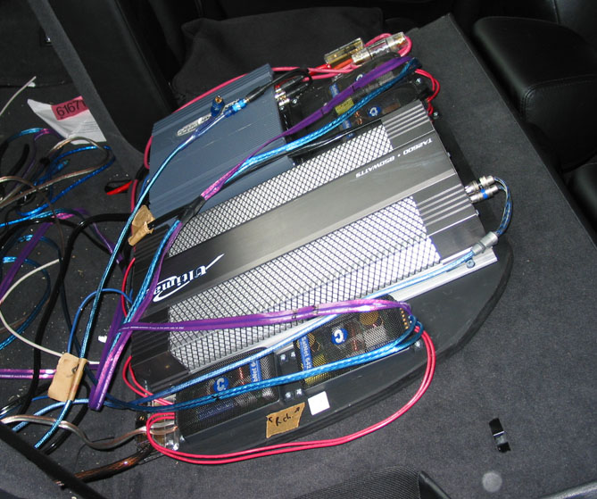
The 3/4" plywood panel is cut to shape (rectangular except curved on right side) and positioned so it doesn't interfere with the seat operation, but gives maximum area for mounting electronics. It is quite packed, and there is only about an inch or so of clearance around it.
I drilled five or six clearance holes into the plywood for screws holding it to the back of the seat. The metal of the seat back is very hard. When drilling it, be careful it doesn't suddenly punch through and damage the seat from behind. Also, if the holes in the seat back are not the correct size for the screws, they will get so tight that they will break off when you try to tighten them. The material is so hard that the screws will not expand it. After I got it to fit, I painted the wood black.
The 4-gauge positive power wire (red) is coming from the left side of the car, under the carpet in the floor of the trunk, and then up the left side of the panel. A distribution block for positive is at the upper left corner of the panel (facing it). This feeds a 30A fuse for the subwoofer amp, and the main channel amp directly (since it has two fuses built in). These are just visible around the red wiring at the very top of this picture. Ground comes into the panel at its lower right via a 4-gauge brown wire (which came in the amp wiring kit). There is a distribution block for ground at the lower right of the panel as you face it (bottom, near in the picture, below the Right Channel crossovers). I used 8-gauge stranded black and red wire coming out of the distribution blocks to connect to the amplifiers. The Left Channel crossovers are above the subwoofer amp (the smaller one).
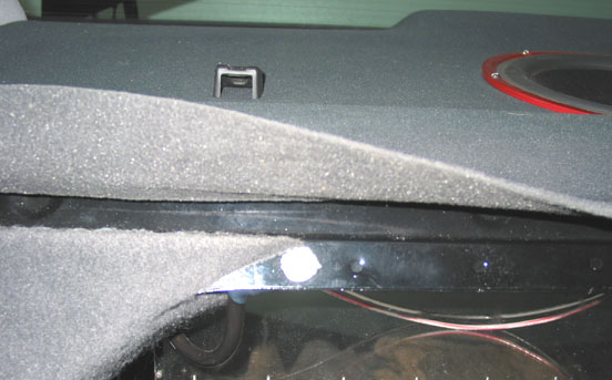
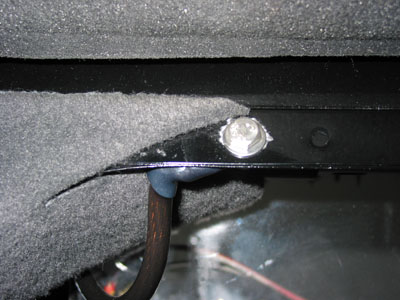
The 4-gauge ground wire (brown) is attached with a 1/4" stainless steel bolt to the car frame. I drilled the hole and used a grinder to remove the paint on both sides of the metal below the parcel shelf as shown in these pictures. The first picture below shows the location of the hole with respect to the parcel shelf (I'm holding the flexible felt trim up), facing toward the back of the car from inside. The second shows the bolt, terminal, and wire. The terminal is on the trunk side, under the nut, which is very securely tightened. Always use stainless steel hardware when possible to protect from the exterior environment. Periodically check the tightness of the bolt and all the set screws in the power terminals, distribution blocks, and fuses. The covers come off the distribution blocks for easy access. A friend explained that a significant voltage drop (more than 1V) can occur simply by not having things sufficiently tight, even though it appeared they were.
The signal wires, speaker wires, and the remote wire run toward the rear of the car on the right side, under the sill trim, up behind the carpet behind the rear seat, then under the parcel shelf and out of a hole in the trunk ceiling in the corner by the ground wire. The wires come down from above. They are collected and held in place with a short (vertical) piece of insulating foam, the kind that is used for insulating hot water pipes in a house (not shown here). I wrapped up the wires with it and put cable ties around them. The wires then come out from that and go to the mounting panel. Running them was a real challenge. I needed to remove the seats and all of the trim (except for the gray carpet behind the seats, which could be loosened but did not come off), and run the entire length of all the wires in stages, coming out of holes in the car body, and then refeeding them back in to reach the next hole, etc. until I arrived at the final destination. Several times I had to fish a nylon string in, then tie that to the wires to pull them through.
Wiring detail (taken from inside trunk, facing the front of the car, right corner):
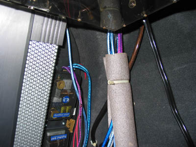
In this picture, I still hadn't cleaned up the wiring, but you can see how the wires all come from above, then are collected, and go down together at the front right corner of the trunk just behind the right edge of the right rear seat before they lead to the electronics panel. The subwoofer enclosure is visible at the top of the picture (the large 12-gauge black wires on the right are driving it).
Here is the main fuse holder (with 80A fuse) mounted on the top of the battery cover in the engine compartment using small stainless steel screws with nuts on the inside:
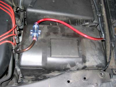
A gold terminal is bolted to the battery terminal (under the cover; not visible) and a short length of 4-gauge wire leads to the fuse holder. The 4-gauge red wire is one continuous piece going to electronics panel in the trunk. Much of it is covered with the ribbed plastic sleeve, starting at the side of the battery case and going back all the way to the firewall.
I did not install one of those large capacitors in my system. I believe I don't draw sufficient power to need one.
Fortunately, I did not need to modify the charging system.
Links for detail pages and illustrations:
Front Speaker Installation Details
Subwoofer Installation Details
Amplifier and Wiring Installation Details
Back to Audio Installation Page
I am the owner and technical administrator of the Official Blondie Web Site (http://blondie.net).